
Link Aggregation on HP Comware
Instructions for how to set up a link aggregation on HP's Comware (not Procurve).


Using link aggregation allows equipment to be joined together at speeds greater than a single link would provide. In essence, link aggregation bonds the connections together, providing the sum of their speeds. In this tutorial I'll cover how to do this with HP Comware.
Why use Link Aggregation?
With 10 gigabit per second (Gbps) connectivity becoming more common on business and enterprise equipment, it may come as a surprise that link aggregation is still used. Consider though that you don't only have to bond 100 megabit per second (Mbps) or 1 Gbps interfaces[1] - you could bond the 10Gbps interfaces too. Link Aggregation is used whenever you want to increase the connection speed beyond a single link's speed.
This first diagram shows two switches linked together with four connections, without link aggregation. In this configuration the switches have probably have been overwhelmed by broadcast storms unless something called Spanning Tree has been enabled or there's some other setting in place to separate the links:
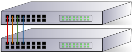
Instead we tell the switches to treat the four cables as one big cable, increasing their bandwidth (as mentioned before) and preventing the broadcast storms issue.
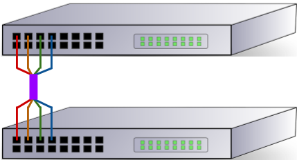
Another key advantage of bonding multiple interfaces / connections together is fault tolerance. Traditionally you would have one network connection to each device, generally provided by one cable. If that cable fails the device goes offline, and while that may be acceptable for your end user's PC it's far from agreeable when it's the company's main file server that's gone offline! In situations where you have a stack of switches, where multiple switches participate in a group and act as one, you can also link aggregate across the different switches, providing redundancy for both cable and switch failure.
Not just for switch to switch
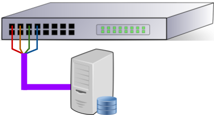
While you'll often find link aggregation used to increase the up-link bandwidth between switches, it's also important to consider that you can use link aggregation to get a better speed from your switch to your server. Virtualisation environments are a great use case for this, meaning the virtual machines on the host aren't all sharing a 1Gbps link.
Different types of Link Aggregation
Not all aggregated links are created equal, and HP Comware allows for two different types - static and Link Aggregation Control Protocol (LACP).
A static aggregation has no intelligence behind it. Configuration on the two devices says "these interfaces are bonded together" and the link either comes up or it doesn't. This is the default type when creating a link aggregation on HP Comware.
LACP, on the other hand, employs a degree of intelligence and can negotiate with equipment at the other end. There's also an element of link health checking that occurs over an LACP link to keep the connection in as good a state as possible. I'm not an expert in this field, so if you're interested I'd encourage you to read about it further (e.g. on Wikipedia).
Setting up the Link Aggregation
First connect to the switch over SSH and enter the configuration terminal by issuing conf t. Note that when in configuration mode we can make changes, and our prompt will change from > to #.
The code sample below creates our aggregated link (called a Bridge-Aggregation) with ID 125. Next a description is set - not mandatory but does make our configuration easier to read.
In this example I've chosen dynamic as the link aggregation mode. This means the link will use Link Aggregation Control Protocol (LACP) to add some intelligence to the link. If you omit this line the link will be static.
# interface Bridge-Aggregation 125
# description Server Link
# link-aggregation mode dynamic
Adding ports
Once our bridge aggregation interface exists we have to add physical connections to it, otherwise our link cannot be used and will have no speed. Each port should have the same speed and duplex setting (e.g. each should be 1Gbps, full duplex) and should be on the same VLAN.
In my example I've got two switches in the same Intelligent Resilient Framework domain (IRF domain). This is a feature of HP switches that allow you to connect several switches of the same model together and to manage them as a single device. IRF is outside the scope of this blog post. The important thing to note here is that my configuration will provide me with both link and switch fault tolerance.
After switching to the configuration terminal, enter the interface's configuration via the interface command. Again I've specified a description for ease of management and then I've added the interface to our bridge aggregation's virtual interface using port link-aggregation group. These physical ports have no other configuration applied to them at the moment.
# interface GigabitEthernet 1/0/29
# description Server Link
# port link-aggregation group 125


# interface GigabitEthernet 2/0/29
# description Server Link
# port link-aggregation group 125
Set the Bridge-Aggregation VLAN
When setting the VLAN on the Bridge-Aggregation virtual interface (Bridge-Aggregation 125in the example above) that VLAN is applied to all the physical interfaces, so we only need to apply the config once. In the snippet below we're placing Bridge-Aggregation 125 onto VLAN 30:
# interface bridge-aggregation 125
# port access vlan 30
Verifying the link aggregation is up
There's two methods we can use to see the status of our bridge-aggregation interface. First there's the display link-aggregation verbose command, which allows us to look at a specific link:
> display link-aggregation verbose Bridge-Aggregation 125
Loadsharing Type: Shar -- Loadsharing, NonS -- Non-Loadsharing
Port Status: S -- Selected, U -- Unselected
Flags:  A -- LACP_Activity, B -- LACP_Timeout, C -- Aggregation,
        D -- Synchronization, E -- Collecting, F -- Distributing,
        G -- Defaulted, H -- Expired

Aggregation Interface: Bridge-Aggregation125
Aggregation Mode: Static
Loadsharing Type: Shar
  Port             Status  Priority  Oper-Key
-----------------------------------------------------------------------------
  GE1/0/29         S       32768     10
  GE2/0/29         S       32768     10
In the above sample we can see the aggregation mode is static, and both interfaces GigabitEthernet 1/0/29 (shown as GE1/0/29) and GigabitEthernet 2/0/29 are selected - they're in the aggregation group correctly. Because this is a static link there's no additional information on the link itself.
For dynamic links (set with link-aggregation mode dynamic) there's a lot more information, including the ID of the remote system and the ports in use at the remote end:
> display link-aggregation verbose Bridge-Aggregation 121
Loadsharing Type: Shar -- Loadsharing, NonS -- Non-Loadsharing
Port Status: S -- Selected, U -- Unselected
Flags:  A -- LACP_Activity, B -- LACP_Timeout, C -- Aggregation,
        D -- Synchronization, E -- Collecting, F -- Distributing,
        G -- Defaulted, H -- Expired

Aggregation Interface: Bridge-Aggregation121
Aggregation Mode: Dynamic
Loadsharing Type: Shar
System ID: 0x8000, 5c8a-38a8-6387
Local:
  Port             Status  Priority Oper-Key  Flag
-----------------------------------------------------------------------------
  GE1/0/13         S       32768    2         {ACDEF}
  GE1/0/18         S       32768    2         {ACDEF}
Remote:
  Actor            Partner Priority Oper-Key  SystemID               Flag
-----------------------------------------------------------------------------
  GE1/0/13         2       65535    1         0xfffe, 2880-23b7-1f3a {ACDEF}
  GE1/0/18         1       65535    1         0xfffe, 2880-23b7-1f3a {ACDEF}
Looking at the details for the dynamic link there's also information on the link, shown in the Flag column. What these flags mean are beyond the scope of this blog post, but ACDEF is good (see the explanation just after the command for details).
We can also verify the aggregation's speed with display interface:
> display interface Bridge-Aggregation 125
 Bridge-Aggregation125 current state: UP
 IP Packet Frame Type: PKTFMT_ETHNT_2, Hardware Address: 5c8a-38a8-9738
 Description: Server Link
 2Gbps-speed mode, full-duplex mode
 Link speed type is autonegotiation, link duplex type is autonegotiation
 PVID: 30
 Port link-type: access
  Tagged   VLAN ID : none
  Untagged VLAN ID : 30
 Last clearing of counters:  Never
 Last 300 seconds input:  0 packets/sec 40 bytes/sec    0%
 Last 300 seconds output:  41 packets/sec 4123 bytes/sec    0%
 ...
This is a handy check to make, as if you've bonded three interfaces, but the speed doesn't show as three times a single interface's speed you know you have a configuration issue.
A note on VMWare (non-distributed switches)
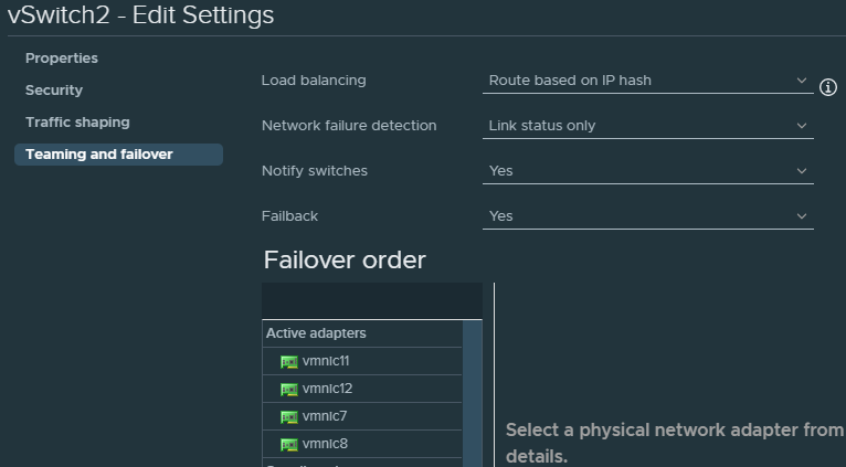
Note that if you're using VMWare ESXi, but you're not using distributed switches, that you can only use static link aggregation. If you want to take advantage of LACP you'll need to set up distributed switches.
Further, you will need to configure your vSwitch to use route based on IP hash for the load balancing mechanism:
Conclusion
Link aggregation is really useful for providing redundant links and increased bandwith between devices. On HP Comware the biggest issue I've encountered is knowing when to use the terms link-aggregation and bridge-aggregation as HP seem to chop and change!
Banner image: my link aggregation diagram
[1] Here, an interface is a network connection on an item of networking hardware. For example, an RJ45 socket on a network switch.
Switch image: https://www.needpix.com/photo/87646/switch-network-lan-computer-communication-technology-connection-ethernet-equipment
Server image from OpenClipart (before it went offline)