
Raspberry Pi Zero humidity sensor using MQTT: part 1
The first step in building my kitchen temperature and humidity sensors.


As I mentioned in my blog post about Home Assistant on a Pi 4, one of the key reasons for playing with Home Assistant was that I wanted to be able to monitor for leaks using a humidity sensor. In this post I'll take you through installing Raspberry Pi OS and building the hardware, before discussing the software side of things in a future post.
Thanks to Emmet at Pi My Life Up as his instructions were greatly helpful for this stage of the project.
The hardware
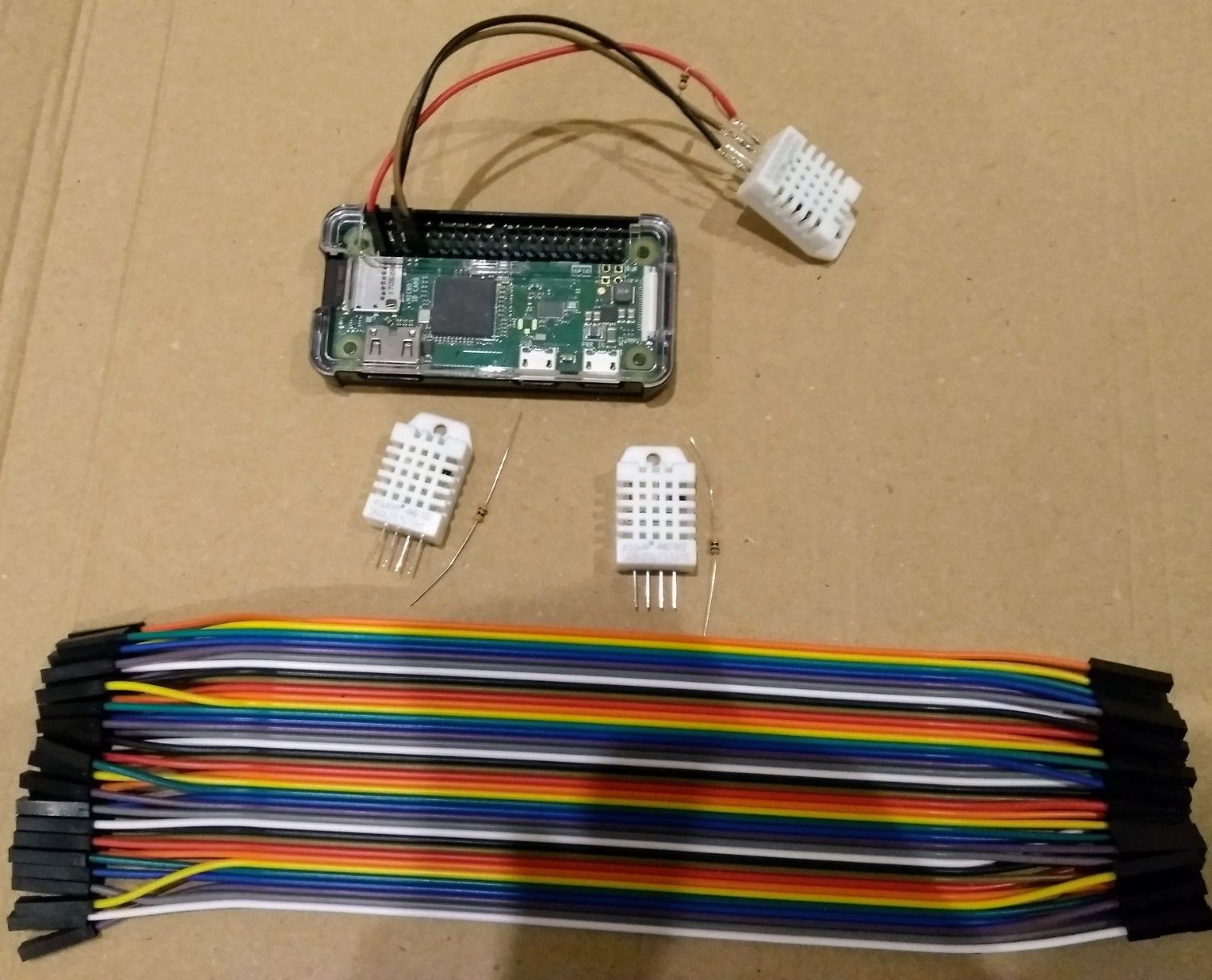
For this project I'm using a Raspberry Pi Zero W (the model with wireless and Bluetooth built in) along with the Adafruit DHT22 humidity and temperature sensors. I want to monitor the humidity in three locations so I've actually got three DHT22 units to wire up and retrieve data from.
Install Raspberry Pi OS
Formerly called Raspbian, Raspberry Pi OS is a Debian based operating system for the Rapsberry Pi. Installation is pretty painless: simply download the image (in this case a software image - a copy of an installation) from the website and then write the image to the microSD card. As a Linux user I did this using the dd command line tool, and there are some good instructions here. For those prefering a graphical tool the Rapsberry Pi Imager is also available.
As this Raspberry Pi is going in a cupboard, with no monitor attached, I opted for the "lite" version of Raspberry Pi OS - command line only.
Configure WiFi and SSH
Once the image is written to the microSD card we need to configure the installation. One option is to connect a keyboard to the Pi Zero, insert the microSD card, turn the Pi on and configure it from the command line but I didn't have a micro USB to USB A cable so that wasn't an option. Fortunately it's possible to configure WiFi and SSH from a different computer before booting the Pi Zero.
After the image has copied to the microSD card you'll see the card shows as two removable drives. Windows users will have been warned that one drive "needs formatting" before use (don't do that!!) while the other is called BOOT. It's BOOT that we'll be making our changes to. First we'll enable SSH as that's the easiest of the two steps. Open the BOOT drive (using My Computer / Computer / Finder / whatever) and create a text file just called ssh - no file extension. When the Pi boots it will see this file and enable SSH (more details here, section 3).
Next to configure WiFi by creating a file called wpa_suplicant.conf in the same place we created the ssh file. On boot the Pi will read this file, copy it to the correct location on the main drive and then apply the configuration. An example config looks like this:
ctrl_interface=DIR=/var/run/wpa_supplicant GROUP=netdev
update_config=1
country=GB

network={
 ssid="Jonsdocs"
 psk="A long example password that is not real"
}
You can read more about that here.
Now it's time to put the microSD card into the Pi Zero and to let it boot. The Pi will automatically join your WiFi and you'll need to find its IP address (check your router's DHCP leases or use a network scanning tool). Connect to the device using SSH and logging in with the default username (pi) and password (raspberry). Windows users will find PuTTY a useful tool here. I recommend you change the password with passwd pi and then following the on-screen prompts.
Setting a static IP address is a wise idea at this point and I recommend the tutorial on The Pi Hut's website. If you're familiar with Debian you can follow usual methods.
Connect the sensors
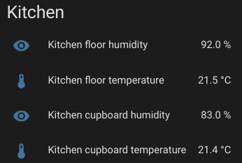
At the time of publishing this post I've got two out of three sensors connected to the Pi Zero. One of them may have a problem with the humidity reading as it's consistently registering a lot more than the other (at one point 90% vs 77.1%). Ignore the locations in the screenshot - both sensors are in the same place at the moment.
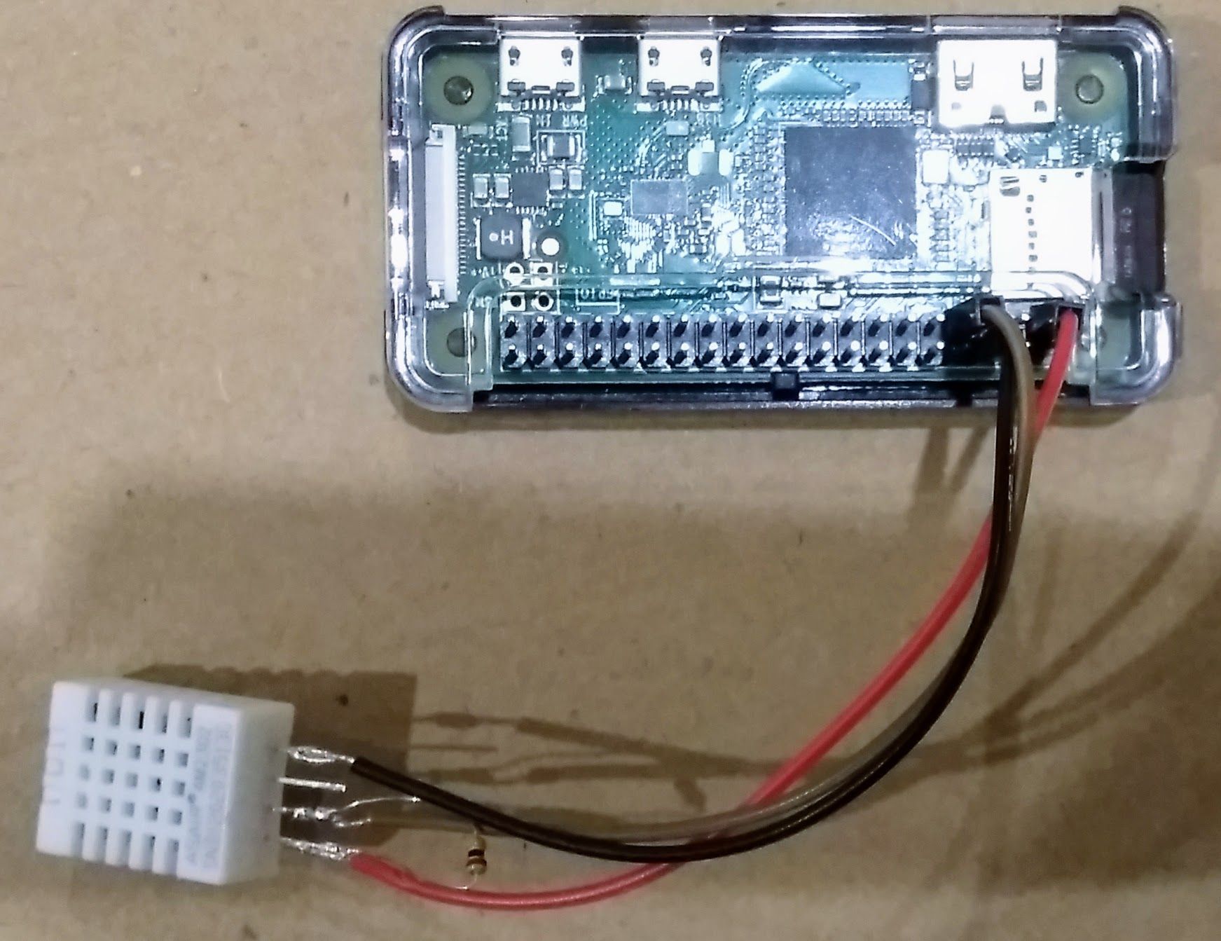
For the first sensor I've just (inelegantly) soldered the sensor to some short wires and connected it to the Pi's 3v3, ground and GPIO pins.
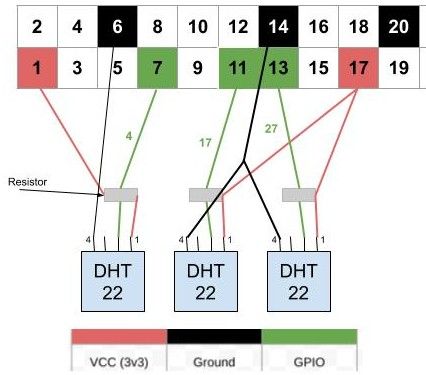
GPIO pins allow you to tell the Pi to query data from the sensor in order to get a reading. The DHT22 sensors only use one pin for sending data (pin 2) so, theoretically, you could connect 20 sensors or so. The bigger issue at that point would be power. There's only two 3v3 pins so I've spread my three sensors between them using a branched cable (the wiring diagram in the next section is easier to understand). Similarly I've chosen to share a ground for two of the sensors.
You can see the pinout for the Pi by using the pinout command[1]. It's not installed in the "lite" OS image but you can install pinout by using sudo apt install python3-gpiozero. If you prefer a graphical solution in your browser there's pinout.xyz.
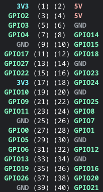
pinout command run on the Raspberry Pi Zero.Wiring diagram
If you want to build the same project then the wiring diagram below should be useful. As you can probably tell, drawing schematics isn't my strong point (particularly not with a track pad!). The green numbers identify the GPIO number (not to be confused with the pin number) that we'll reference later in the script.
Future improvements
Longer term, once everything is working correctly, I'll likely encase the solder joints at the sensor in hot glue to protect them, as this isn't my best soldering ever (soldering directly onto the DHT22 pins is very fiddly!). Alternatively, and probably the better option, will be to get a printed circuit board (PCB) made up (or find a pre-made one) that's got a female header on it. I can then solder the sensors to the PCB and the header will securely fit on the Pi's corresponding connector. At the moment the connections to the Pi's header aren't the most robust.
Connecting to Home Assistant
Next it's time to make the sensors' data available to Home Assistant. This requires some scripts that I'll cover in my next post (don't worry, the code will be provided!).
Banner image: My proof of concept setup.
[1] https://gpiozero.readthedocs.io/en/stable/installing.html
Disclaimer: Following this blog post to make your own sensor is undertaken at your own risk. Soldering irons are hot and will cause serious injury.